For the last 5 years, I was a co-founder at Advanced.farm. One of the most rewarding experiences was building the vision system for our fruit harvesting robots. This was a challenging, multi-disciplinary project that required clever solutions to meet the demanding needs of life on a farm.
Application
We were pretty set on using a depth camera in a “Eye in Hand” type application. To us, this meant putting the camera on the end effector, right next to the gripper. We liked this approach because:
- From a controls perspective, it removed a lot of the error from the system. We didn’t have to care about how much error stack-up was in the robot kinematic or mounting.
- We wanted the ability to improve our vision system by looking at the scene from different angles.
- We were paying a lot of money to have a robotic arm that could pick the berries. We wanted to use that platform to its fullest extent.
- The strawberry plants were often very bushy. We could work around occlusions if we could move the camera around.
- We thought this ability to move the camera around matched better with what we saw humans do in the field.
- We needed both depth and color images from this camera. This was relatively uncommon in stereo cameras at the time (they mostly used monochrome imagers).
Build vs Buy
Our goal from the start was to buy a vision system solution. This seemed like a pretty straight forward build/buy decision in the buy column. There were plenty of vendors making cameras and some of those made depth cameras - like the Intel Realsense. We should be able to take one of those - strap it to the end effector - and bada bing bada boom - we’re picking strawberries.
Buy - Attempt #1
The first camera we tried was the Intel Realsense SR300.
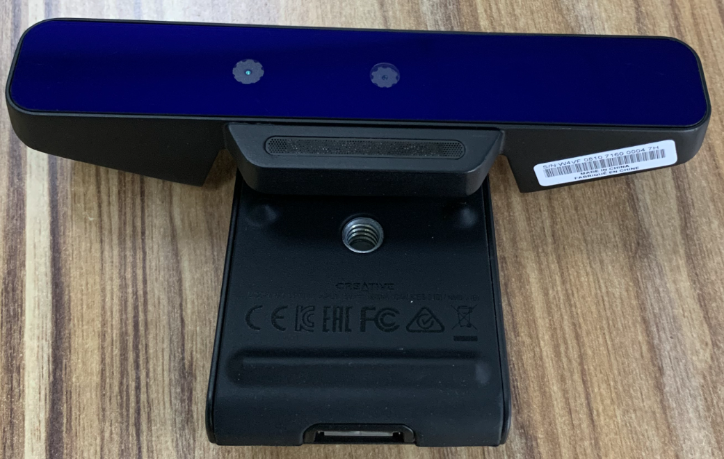
This camera provided depth and color images but had some issues:
- It used a structured light approach - meaning there is a laser projector and an imager that receives the reflection of the laser from the scene.
- The depth imager and the color imager were not well synchronized together.
Build - Attempt #1
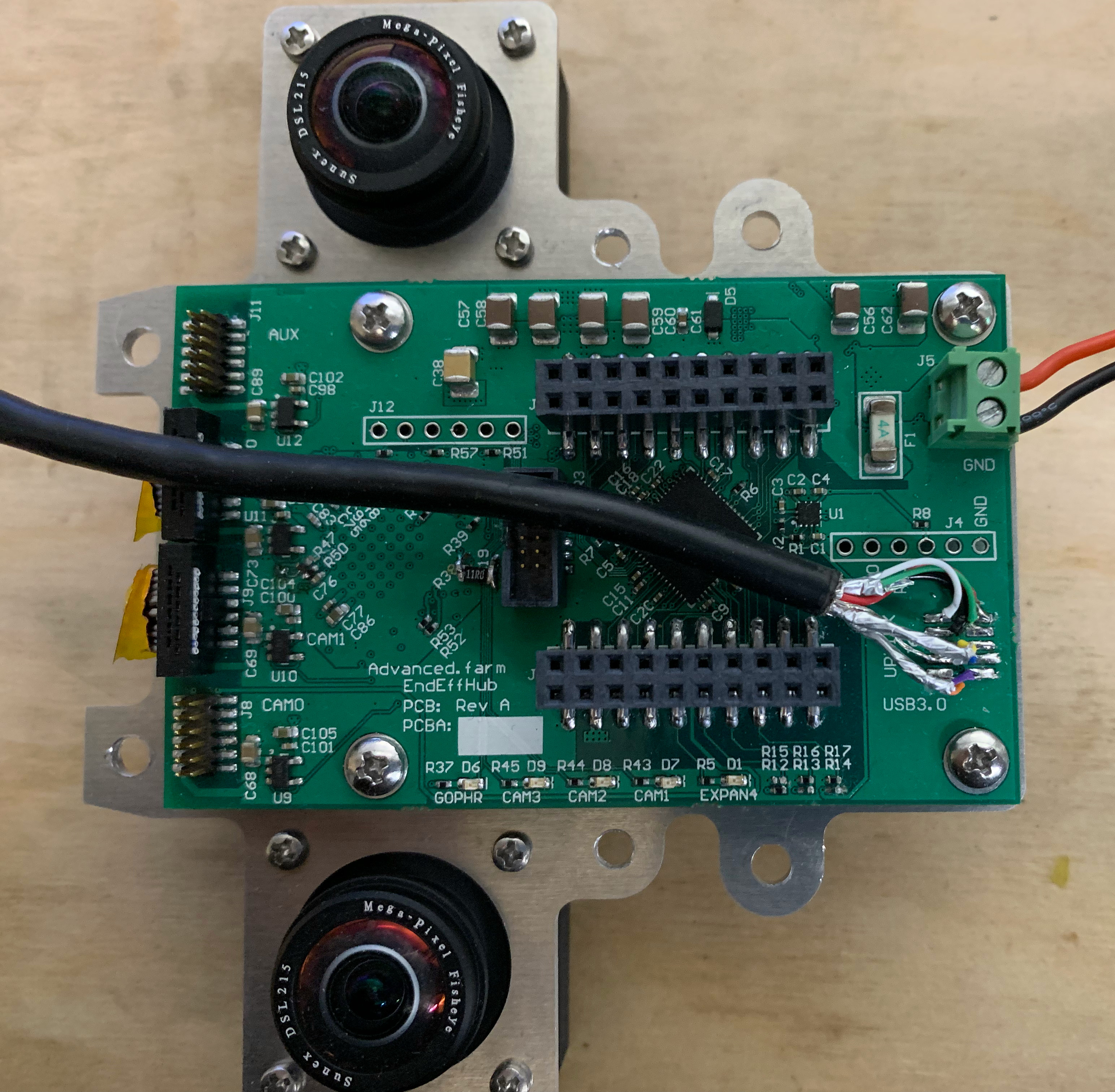
After that disappointing experience with the SR300, we decided to re-evaluate the build/buy decision. Surely we could find camera modules that could meet our needs to build a stereo camera in relatively short order. We already needed an embedded system at the end of effector for sensing vacuum, finger readings, etc. We could combine these efforts and reduce the total mass at the end of the arm to boot.
We went about designing a system consisting of the following:
- Two Basler daA1280-54uc camera modules
- These camera modules had global shutter color imagers.
- They also had a hardware trigger interface.
- USB3.0 interface for data transfer.
- Microchip, USB5807 - 7-port USB 3.1 Hub IC
- Combined the data streams for both cameras and the sensor controller.
- Allowed us to run one USB3 cable down the arm
- ATSAM4S microcontroller
- USB Interface with a bootloader on the USB - This would allow us to field upgrade ad nauseam.
- Plenty of IO and ADCs for the sensors we needed to measure.
- This also provided the camera’s hardware trigger on a configurable time.
We used the Basler Pylon library to capture images from the camera. I was very impressed with their documentation and the quality of this library.
OpenCV’s stereovision libraries contain various functions and workflows to convert the captured images to depth. We started using the semi-global block matching (SGBM) to generate a full depth frame. The hardware triggering mechanism and global shutter were critical for high accuracy at high speeds.
The other benefit for this approach was choice of optics. We weren’t stuck with whatever trade-off Intel had decided to make. We selected wider field of view lens that allowed us to see more of the plants and strawberries. We could optimize the baseline and resolution for the typical distances were needed to measure.
This worked really well for a time. We were able to raise our Series A based on the performance of the robot with this configuration. It was not without problems though:
- It was a prototype so there were plenty of problems and stupid decisions made along the way - mostly with regard to reliability.
- Water ingress was a real pain point that we solved by shmooing the enclosure shut. The problem was then that water would enter through the USB3 connector!
- We decided to get too cute with our short stub connections from the Basler camera to the hub board. Our multiple attempts at this all either failed reliability tests or were too hard to manufacturer.
- Needing two connections per camera (USB3 + 50mil pitch 2x3 header for trigger) was very inconvenient.
- We didn’t like USB3 but there wasn’t much we could do at the time. This would become a common theme.
Buy - Attempt #2
Around this time, the Intel Realsense D435i came out. It looked very promising. Instead of structured light, they had switched to a stereo-based approach with two monochrome imagers. They had a 3rd color imager that they claimed was “synchronized”.
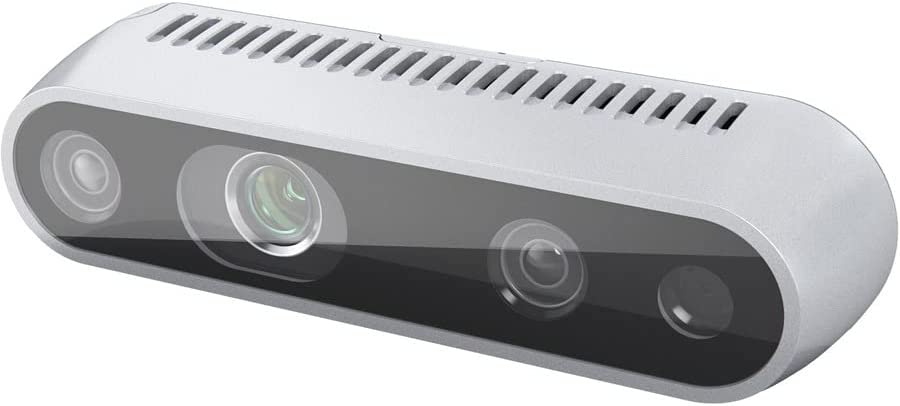
This module was pretty great. It was certainly much more productized than anything we had built at that point. Leveraging the many man-years of work that Intel’s team put into this should have been a slam dunk. We still had major concerns:
- The device still used USB3 for communications.
- The optics were very limited in their field of view.
- The minimum observable depth was just outside of the nearest depth we wanted to measure.
- The module was not ingress protected - so water intrusion would still be a problem.
Despite all of these misgivings, we decided to give it a shot. The mechanical team worked on a better cable chain to protect the USB3 cable and an enclosure to protect the camera from the elements. The software team start integrating the new camera model into the stack. On the bench everything looked good - lets get it to the field.
USB3 - Where all bits go when they die
The most troublesome issue with the D435i was the USB3 interface. As our robot’s moved to scan the strawberry beds, we would bend the USB3 cable back and forth many times. We sourced high flex rated USB3 cables from Cicoil and Igus. We followed the datasheet’s recommendations on minimum bend radius. We did everything we could think to keep these cables running.
During operations, we were replacing USB3 cables every 1-2 weeks due to wear.
We attempted to use a USB3 over fiber optic solution (not this but something like it). The transceiver on the end effector side would overheat and drop the link every so often requiring a restart. Not sure if the plastic fiber would have stood up to flexing many cycles - we never got a chance to really try.
There was no way for us to operate profitably if we couldn’t keep the cameras running.
Build - Attempt #2
With all of this new found knowledge under our belt, we decided to commit to a build that we thought could solve our problems. At the time we saw the requirements as:
- 2 Color Imagers providing Stereo at a baseline of our choosing.
- Global Shutter
- Synchronized hardware triggering
- High flex cable with as few wires as possible.
- Minimum of 5M cycles.
- Low mass.
- EEPROM for storing lens calibration parameters.
- Ingress protection to IP65 - we would not clean the cameras with a pressure washer, but they needed to not die if they got wet.
With these constraints - I set to work finding components that could meet our needs.
Here is a block diagram for the top level of the camera solution:
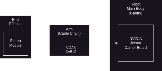
The “End Effector” was the part that grips the berries where the camera was mounted. The arm was an actuated tube that allowed us to move the end effector around the workspace. The “Gantry” was the robot’s main body where the compute, power, and motors were stored.
The camera would consist of two components:
- The “Stereo Module” was a custom PCBA and enclosure at the remote end effector. We wanted this to be as low mass as possible so we decided to put as little compute at the end effector as possible.
- The “Carrier Board” was a custom PCBA that provided the mezzanine connection to a NVIDIA Jetson compute module.
- We started with the TX2 and eventually moved to the Xavier AGX.
- This board assembly was mounted in the gantry.
- We decided to use a single coaxial cable to connect the two sub-systems.
- For our application there was very little twisting of the cable - mostly just bending. Coax seemed like an optimal fit for this.
- We could source high flex rated Coax cable in the 5M cycle range. We were still skeptical of these specs but we figured with less connections this had a higher likelihood of meeting that spec.
- With frequency domain multiplexing, we could put power and comms on the same coax line and reduce the total number of connections.
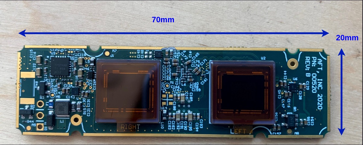
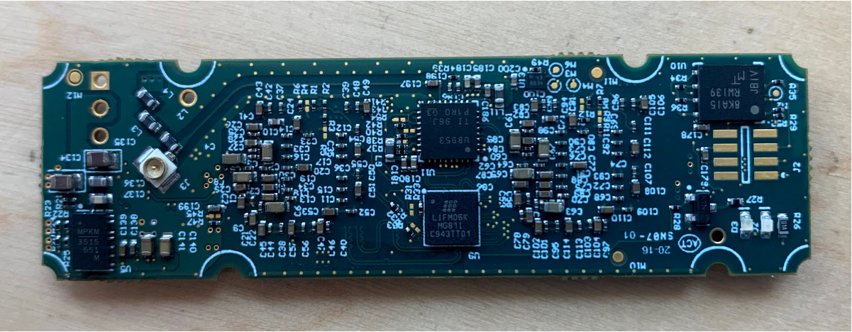
Stereo Module
Here is the block diagram of components for the stereo module:
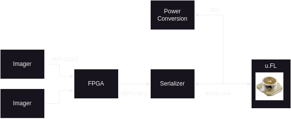
Major Components
- Sony Imagers
- Global Shutter
- High resolution supporting 60fps
- Lattice Crosslink FPGA 1. This chip was made for video bridging applications and was perfect for our application. 2. Various IP to support applications.
- Texas Instrument’s FPDLink III - Serializer
- Up converts the camera interface to a high frequency (RF) serialized format.
- This gets converted back to the camera interface format on the other end by a “Deserializer”. The “Serializer + Deserializer” link is refered to as a “SerDes” link.
- Also provides an I2C back channel (not shown) for command and control of the imagers/FPGA.
FPGA Programming
One of the issues that we had encountered with the Basler module based stereo camera was desynchronization. Even when we were hardware triggering simultaneously, the images read in software would get out of sync. Because each basler camera was on a separate USB port, each camera was opened as a separate device. Software bugs would sometimes creep in and we would have to run a synchronization sequence before processing frames again.
With the custom stereo module, I planned to resolve that issue once and for all by combining the two images into one big H-stacked image frame in the FPGA.
I used Lattice Diamond and Aldec Active-HDL to write a VHDL implementation that would accept image data from both imagers. I ended up adding an I2C device interface and a pattern generator in the FPGA as well. This proved very helpful for debugging any connection issues in the future.
Jetson Carrier board
The carrier board would serve the purpose of decoding the serialized RF link and presenting the image data to the NVIDIA Jetson.
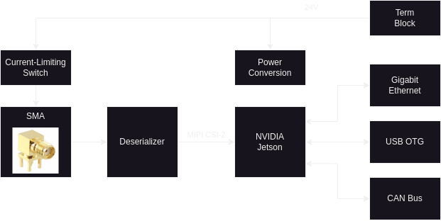
Major Components
- Texas Instruments FPDLink III Deserializer
- Received the camera data and fed it to the Jetson.
- Multi-camera support.
- NVIDIA Jetson TX2
- Our first prototype targeted the TX2 as that was available in an industrial version.
- The Xavier AGX hadn’t come out with the industrial temperature range version yet.
- Ultimately this didn’t matter - we ended up using the commercial temperature range variants anyway because that was what we could source during the pandemic.
- In hindsight, we probably should have just targeted the Xavier AGX from the beginning.
- The TX2 had an integrated gigabit ethernet PHY so all we had to do was add a RJ45 connector.
- The goal of the CAN bus interface was to integrate the robot control bus for timing synchronization.
- I wanted to use the Sensor Processing Engine (SPE) to generate our sync packet.
- The SPE is a small ARM microcontroller on the same die as the 4 ARM64 cores.
- We ultimately did not have time to implement this feature.
- Our first prototype targeted the TX2 as that was available in an industrial version.
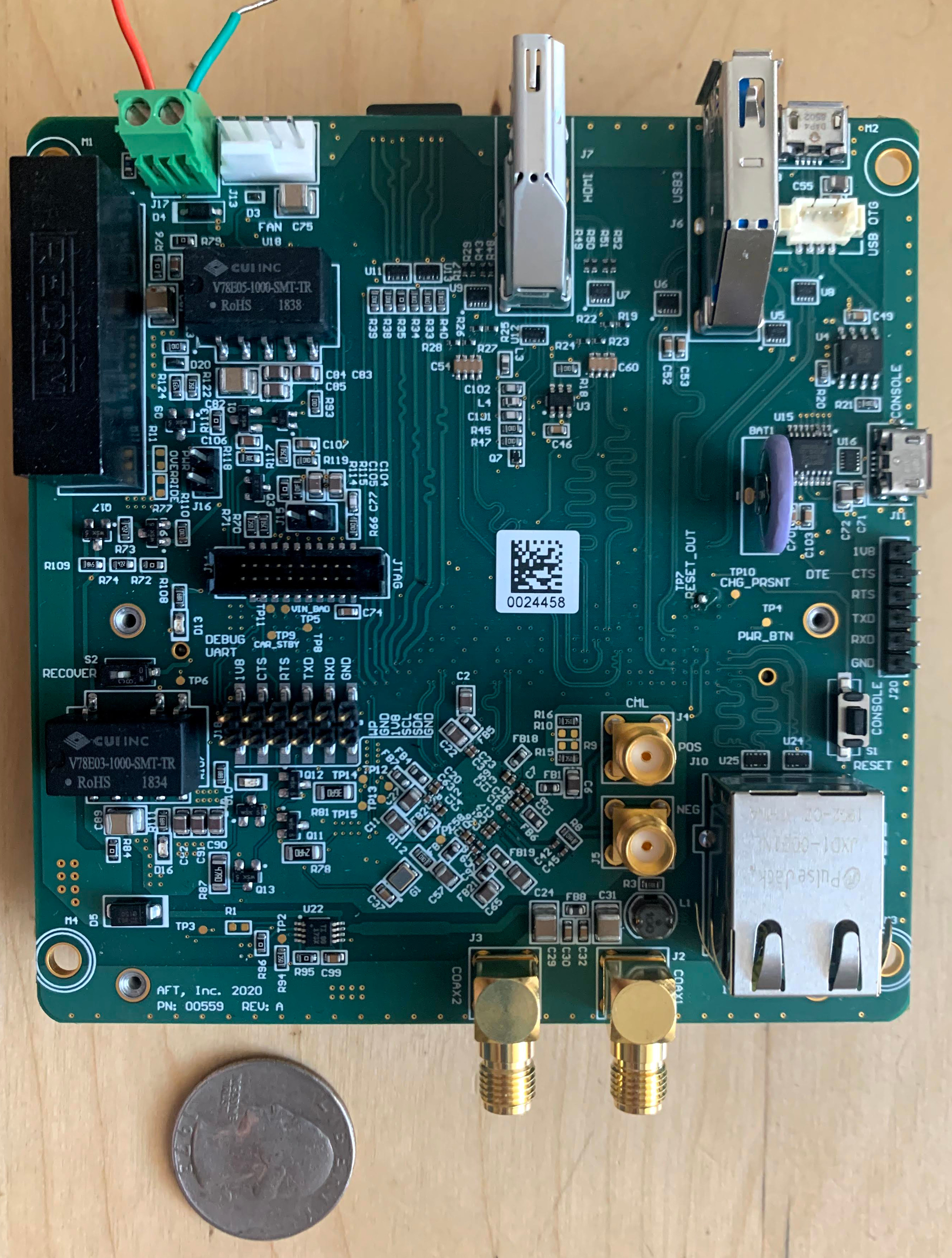
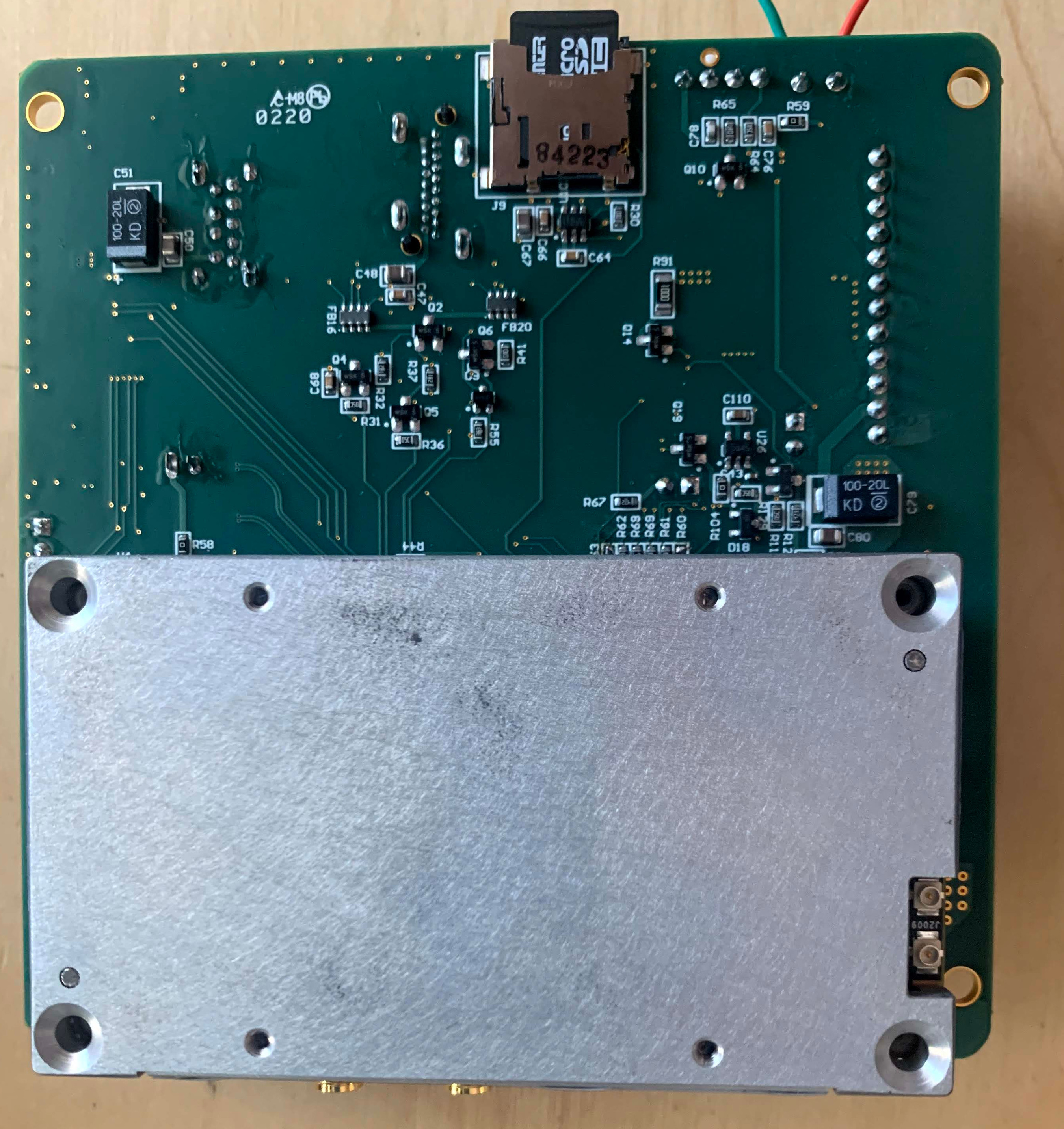
Notes on the prototypes:
- Ultimately, we ended up DNP’ing the HDMI, USB3, and JTAG connector.
- The HDMI/USB3 worked but wasn’t really useful for our application.
- We could ssh in via the ethernet or the USB OTG interface.
- The OTG interface end up being our primary access point because it allowed access with a single USB micro-B connection.
- In previous compute iterations, we ended needing a “Crash Card” that was basically a KVM we could plug into a laptop and then plug into the HDMI/USB ports of the computer. With the jetson’s USB OTG, we didn’t need any of this.
- The JTAG interface was never really any use. From my understanding you needed a Lauterbach ICE and we didn’t want to spend the money.
- I placed SMA 2-ports for expandability. I was thinking of a future case where we might want to mount a camera on the gantry or in a global positon.
- I placed a small Lithium cell for the RTC backup. The TX2 had a circuit to both pull juice when off and then charge it back up when powered.
- The Orin series does away with this circuit and can’t charge the cell.
- Ultimately, it didn’t really matter. We used chrony to synchronize the clock of the jetson with the master node.
- The jetson module has a set of signals on boot up that tell the carrier board when it can power up.
- We used the auto-power-up mode so that we didn’t need a power button. The Robot powered up and so did the jetson.
- I added a pull-down jumper on the carrier power enable signal so that I could test the circuits without the Jetson connected. This saved a lot of time.
- The Jetson has limited non-volatile memory storage so I added a microSD card interface thinking that would be useful for testing/debugging in the field
- This didn’t end up being as useful as I thought.
- On the harvester, we setup an NFS mount from the jetson cameras to the master computer.
- This allowed us to dump video from the camera over the network to the master computer where we had some large spinning rust.
- Sourcing issues during the pandemic was one of the most painful part of this whole experience.
Software
Now that I had a hardware platform to work from, I could start working on the drivers. There were a hand full of example drivers for the deserializer on the internet at the time. I didn’t find any that used the “TegraCam” interface defined in NVIDIA’s JetPack SDK. We were able to get a sample drivers for the imagers from Framos (our vendor for the imagers) but it was written for JetPack v3 and we needed to use v4 for the CUDA version support. The other devices either had existing drivers in the mainline linux kernel or would need custom drivers (like our FPGA interface).
I set to work creating a driver structure that would allow for the camera module to be plug and play. Because of the current-limiting power switch, I should have been able to turn off power, allow a field tech to replace the camera, power the camera back on, and then continue picking with minimal interference. I put the various device that supported the camera in separate kernel modules that could be loaded on demand. Then when the deserializer detected that a camera was connected, it could instantiate instances of those modules and enable camera image streams.
The NVIDIA Jetson platform turned out to be a game changer for our vision stack. We were able to quickly put out ML models that could better detect fruit as well as other features.
Was it worth it ?
I think the answer from the team was a resounding “Yes.”
The camera went from being the most problematic on the pareto chart to being one of the least problematic. We went from needing maintenance once every 1-2 weeks to operating for months at a time without issue.
It took a lot of work both on hardware, software, and firmware to get there but we eventually built a product that not only effectively solved our operations issues but also provided a compute platform for advanced ML integration. This would prove critical for our later entry into apple picking.