Continuous integration (CI) is the gold standard for most software development processes today. This generally means that for every change made to a piece of software, an automated build and test sequence is performed and the results are published for all team members to see. This extremely useful for catching and correcting many bugs before they get to production.
For most of my career in embedded systems, achieving CI for firmware source code has been challenging. Unit and integration testing has always required speciallized hardware and software. It has often been flaky, incomplete, and/or expensive.
I’ve gone through phases where I have used the following approaches:
- Manual testing on the bench top, ie No CI at all.
- Writing special firmware build images for running on the target.
- Using simulators and writing custom simulation extensions for peripherals to test drivers.
- Physical test fixture for integration level testing.
All of these different methods have pluses and minuses.
Your choice of testing platform will depend on your requirements. What do you want to prevent regressions against? For example:
- Functional Regressions
- Performance Regressions
- Preventing the “Brick” scenario & other upgrade related issues.
- Many others…
Manual Testing
Lack of CI is fine if you are a single individual contributor to a particular project. Without the need to interface with others devs, you can eschew the complexity and time of developing a CI infrastructure. Writing documentation about build process and how to reliably test was still important because “Me, 6-months from now” is going to be utterly lost without it.
Most embedded devices are not islands - eventually the bell will toll for thee. Most embedded devices must interface with software on a host computer, connect to the internet/bluetooth, or show information on a screen to a end user. Your options are:
- Extremely rigid interfaces
- Neither the firmware nor the application layers are ever allowed to make interface changes.
- Like most things, that which doesn’t bend, often breaks.
- Document manual procedures
- For simple devices, we can sometimes create a script to test the device in sequence.
- If there are relatively few changes to be made, then this is not overly burdensome.
- Without continous thought though, corner cases will slip through.
Software Only Testing
Many embedded systems will need to do some kind of algorithmic work in addition to interfacing with peripherals or external devices. For example, FFT or digital filters are often pure software functions. These features can easily be tested in a few different methods:
- Build Test on the Host
- Using compile time definitions, you can include code that supports testing the algorithms on the host instead of the target.
- This makes CI integration easy because there is no additional hardware - you just need GCC/Clang/etc and a unit test suite.
- You must be careful about any code using undefined behavior in your compiler
- Example: Shifts on Signed Integer in C.
- If you need to catch performance regressions then you may need to look elsewhere. This won’t be cycle accurate to the embedded system.
- Build Tests on the Target
- Using compile time definitions, build a unit test framework and run the tests on the embedded target.
- At this point, you bring in some hardware requirements:
- You need to pull in an ICE or bootloader to load the test firmware on the target.
- You need a UART, ethernet, Bus Pirate, or some other means to get the result of the test out of the embedded system.
- You need some custom script usually to integrate these target run tests with your CI solution (Jenkins, etc).
- This has the capability to catch performance regressions, but the added complexity will also likely increase the flakiness of the tests.
- Most Microcontrollers (MCUs) are going to have limited Flash and RAM.
- Ideally, you run the tests out of RAM so that you don’t wear out the flash.
- Some of your tests might re-write sectors of flash and so wear needs to be considered in the long run anyway.
- You may have to split your tests up into multiple target images that must be run in sequence. More complexity, more latency.
- Embedded devices often need to be maintained.
- It would be great if everything ran indefinitely, but my experience is that the tests will begin failing until someone can find the time to fix the hardare.
- Unless there is a dedicated resource for this - it will likely fall to whoever surpasses some annoyance threshold first.
- Regardless of which path you choose, these tests will still only cover the pure software functionality. Where the rubber meets the road is the hardware.
Peripheral Mocking
One way I’ve attempted to include hardware testing in this “Software only” approach is to attempt to mock the software interface to the hardware - not the hardware itself. This is different from the “simulator” based approaches below in that the memory map of the process isn’t changing.
Example Peripheral
Many times the BSP or SDK for a microcontroller will come with C headers that define the register map for a peripheral. For example, here is a partial listing from Atmel Studio 7’s SDK for the XMEGA16E5:
/* Oscillator */
typedef struct OSC_struct
{
    register8_t CTRL;  /* Control Register */
    register8_t STATUS;  /* Status Register */
    register8_t XOSCCTRL;  /* External Oscillator Control Register */
    register8_t XOSCFAIL;  /* Oscillator Failure Detection Register */
    register8_t RC32KCAL;  /* 32.768 kHz Internal Oscillator Calibration Register */
    register8_t PLLCTRL;  /* PLL Control Register */
    register8_t DFLLCTRL;  /* DFLL Control Register */
    register8_t RC8MCAL;  /* Internal 8 MHz RC Oscillator Calibration Register */
} OSC_t;
The register8_t is effectively an uint8_t. This gets instantiated later like this:
...
#define CLK                   (*(CLK_t *) 0x0040) /* Clock System */
#define SLEEP               (*(SLEEP_t *) 0x0048) /* Sleep Controller */
#define OSC                   (*(OSC_t *) 0x0050) /* Oscillator */
#define DFLLRC32M            (*(DFLL_t *) 0x0060) /* DFLL */
...
The peripherals directly memory mapped such that you can reference the OSC object and deferencing each of the registers from that constant pointer definition. For example:
OSC.PLLCTRL |= OSC_PLLDIV_bm;
This is a pretty standard method to access peripherals in a MCU environment.
Mocking with C++
To create an emulated peripheral for software testing a driver to the OSC object, one can implement a C++ class that overrides the assignment and cast operators.
#include<cstdint>

// Common Definition used by several peripherals
template<typename T>
class Register {
	public:
		T value;
	 	operator T() const {
			// Callback handler functions here for
			//  reset on read operations.
			return value;
		}

		Register& operator=(T v) {
			// Callback handler here for operation on
			//  assignment.
			value = v;
			return *this;
		}

		// Other operators ...

		Register& operator|=(T v) {
			value |= v;
			return *this;
		}
};

typedef Register<uint8_t> XmegaReg;

class OSC_SIM {
  public:
	XmegaReg CTRL;
	XmegaReg STATUS;
	XmegaReg XOSCCTRL;
	XmegaReg RC32KCAL;
	XmegaReg PLLCTRL;
	XmegaReg DFLLCTRL;
	XmegaReg RC8MCAL;
};

OSC_SIM OSC;
I’m leaving out some details here but fundamentally this allows for the user’s firmware to make assignments in exactly the same way that they would from C code.
Once you have a mocked interface, you can take the fidelity as far as you can stomach. You can simulate register flag clear on write, clear on read, and any other behavior you wish. With threads, you can take it step further and actually implement the behavior the peripheral device itself.
This becomes tedious after a while. And hope to whatever deity pleases you that you don’t have to change microctroller families. Eventually, I couldn’t justify spending the time and energy on these kinds of mock interfaces for testing all the peripheral drivers and application interfaces. It is very time consuming and error prone.
Simulation
One of the many tools in an embedded developer’s arsenal is the simulator. The idea is to create a virtual machine on a standard computer that mimics the behavior of the MCU. You will find simulators in a variety of different places:
- Atmel Studios, MPLAB, other IDEs had built-in simulators for their MCU platforms.
- QEMU was introduced in 2003
- iPhone and Android both have simulators in their devkits
The simulators come in two basic types:
- Full-System Simulators - Simulate with as close to native performance levels as possible with virtualized hardware.
- Cycle-Accurate Simulators - Simulate with hardware level accuracy on things like branch prediction, pipeline stalls, etc.
For firmware testing, you are most likely going to use a full-system simulator due to performance and cost reasons. This means that the result may not be truly accurate to the embedded system performance just like in software only testing.
The other major weakness for simulators is the limited hardware peripheral support. The models stratify:
- Many highly regular and standard interfaces like disks and ethernet will have excellent models and support.
- Internal peripherals like RTCs, Timers, and Interrupt controllers will have good support but unlikely to have perfectly accurate behavior.
- Communication peripherals are less well supported and when they are supported have quirks.
- You run into the same level of effort and tedious development that I describe above for mocking.
- Large complex IP like GPUs will have limited support unless they are highly compliant to specifications like OpenGL, etc.
From a hardware interfacing perspective, the simulator can get you part of the way to a verification platform but it will always be at a serious disadvantage to physical hardware:
- New ARM, RISC-V, etc cores come out every few years. The simulator is always playing catch up.
- RISC-V cores have extensibility and the option for custom instructions. The simulator is always playing catch up.
- New Hardware SoCs are coming out every year - new peripherals, new interconnect - The simulator is always playing catch up.
- FPGA-based systems may reconfigure on the fly - good luck.
External Devices
If you are trying to test against external devices, you now have another set of problems. First, your simulator’s hardware peripheral model needs some kind of IO interface. For example, some UART models will write to or read from a file. Second, you need a model of the external device that can use that IO interface. Third, you need to hope that there isn’t some major issue that would cause these two things not to work together.
QEMU is the only simulator that I’ve seen that attempts to solve some of these issues. There are various subsystems for i2c, ipmi, etc that attempt to provide bridges for talking with external devices. That being said these concepts are not cycle accurate the best that I can tell.
RENODE
The RENODE project seems to take the QEMU simulator approach to its logical conclusion for embedded devices. It attempts to provide a simulator interface with peripheral support for testing drivers and other hardware facing code. This is great and they have clearly done a lot of work. I plan to investigate this further.
Physical Test Fixture
The last and most efficacious type of firmware testing platform is a physical test fixture. These test fixture typically include the device under test (DUT) which is usually the MCU alone or a the whole embedded system. Around the DUT is a whole suite of systems custom designed to emulate the real-world in which this embedded system will reside. This approach has several benefits:
- Your code runs on the same physical hardware as it will be deployed.
- Performance testing is possible and repeatable.
- The peripherals don’t need to be mocked so there is no question of fidelity (more on this later).
- You can re-create real-world conditions and events in a way that you may not be able to do on the target system.
- Repeatable test cases can be created and debugged.
- Extraordinary events that would otherwise be unlikely or difficult to recreate are possible.
These kind of fixtures are often electromechanical systems with a mix of motors, breaks, relays, pneumatics, digital controls, sensor acquisition, and other features.
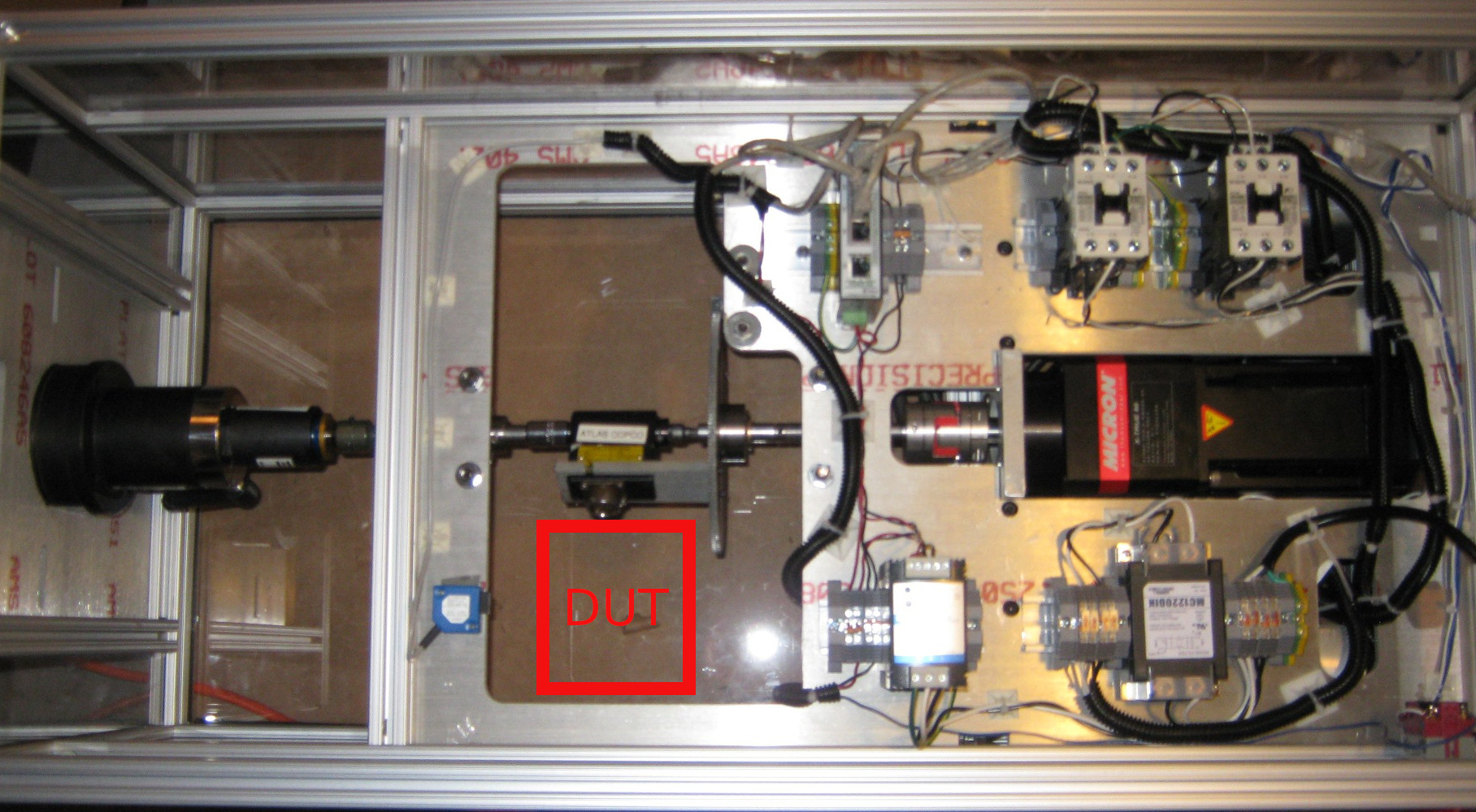
Example Test Fixture
Here is a picture of a fixture I built for a wireless gyroscopic measurement system
Video of the fixture in operation:
This fixture was designed to drive torque through the torque cell in the center while allowing the DUT to be rotated around the center drive axis.
Here is a block diagram of the system:
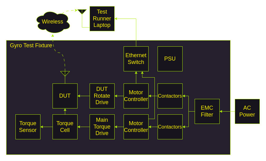
This text fixture allowed us to:
- Measure a controlled torque with the DUT and compare against another control sensor.
- Rotate the DUT while applying a controlled torque and confirm that the measured amount of rotation and profile matched the input profile.
- With the ethernet and wireless interfaces, this provides a full integration test of the software, firmware, and hardware of the DUT.
Cons for Physical Test Fixture
While these types of fixtures tend to expand the testing capabilities, they are not all sunshine and roses.
- These fixtures are expensive to build.
- Requires engineering time, typically among across multiple disciplines, to design, fabricate, and build.
- Requires significant capital to source the components for complex systems.
- Mechanical systems must be maintained so any test fixture (especially one with moving parts) will need maintenance.
- This is one of the larger contributors to flaky and offline test runners.
- Electronic systems aren’t immune - sometimes key components need to be rebooted.
- Flaky tests erode trust in the CI system.
- Because the fixture is expensive - destructive tests are avoided.
- Environmental testing is possible - but also expensive.
- Not many people have or are willing to buy an environmental chamber to devote to this kind of fixture.
- If you want to slew through even two temperatures, it may cause the test sequence to expand from seconds to hours.
- Instrumenting can be difficult
- Let’s say you can recreate an error using the fixture above.
- What if you wanted to measure a particular signal with an oscilliscope?
- At the very least, it is going to be difficult and require like a custom coax cable assembly to snake into the device under test.
- There is still a fair amount of work to write the CI integration
- You will need to write some custom code and groovy scripts to allow jenkins to run the tests for this environment.
- This is another thing that must be maintained with the tool environment.
Is there a better way ?
I want to propose a different way to test firmware. In my mind the requirements look something like:
- High accuracy model of the processor and all peripherals.
- Ability to model external devices like I2C EEPROMs, sensors, etc.
- Ability to simulate analog as well as digital signals - including RF.
- Ability to capture the state of all signals into and out of the MCU with accurate time synchronization.
- Ability to integrate with existing CI solutions with one click.
- Low cost and no moving parts.
- High reliability and repeatability.
In future posts, I’m going to outline what I think a solution looks like.